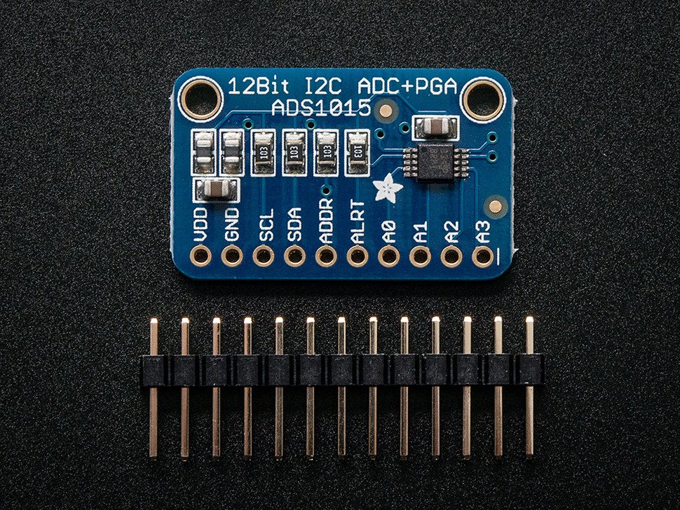
Image by Adafruit
Overview
The ADS1015 can convert up to 4 analog signals to 12bit digital precision. The Raspberry Pi doesn’t have a built in ADC and thus a module like this comes in very handy.
I will be following Adafruit’s guide on how to use the ADS1015 breakout board.
Soldering on the headers
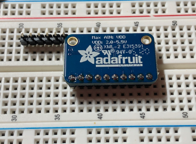
I will be using the ADS1015 in a project and not on a breadboard, thus I will be soldering the headers to point out to the top (like a Raspberry Pi’s GPIO).
I placed the headers inside of a breadboard with the longer leads going into the breadboard.
Then placed the ADS1015 on top of the headers and soldered them in place.
Building a simple voltage divider
To do the initial testing of the module I will be using a simple voltage divider that runs of the 3.3V line of the Adafruit MCP2221A.
I have covered how I use the very handy little Adafruit MCP2221A before on this post and will be using this module again for communicating to the ADS1015 using I2C.
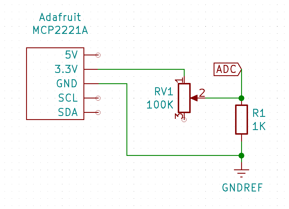
Before moving onto installing the software and testing the ADS1015 I decided to dial in the divider to read +/- 1V at the point where I will be hooking up the A0 port.
NOTE: I tried powering the ADS1015 via the 5V line from the MCP2221A but then Blinka couldn’t detect the MCP2221A module. Connecting it to the 3.3V line seems to solve the issue.
Setting up the software
Please see my post about the Adafruit MCP2221A breakout for how I setup Python projects like these on my Mac.
My git repo for this module can be found here.
- Setup a Python virtual environment and install the required pip dependencies for the MCP2221A.
$ ./new-project.sh

# I then copied the requirements.txt from my mcp2221a directory
$ ./install-requirements.sh
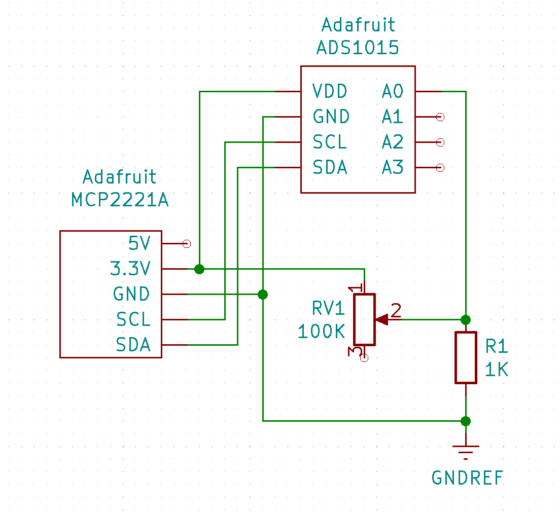
- Connected the MCP2221A to the ADS1015:
- 5V → VDD (White)
- GND → GND (Black)
- SCL → SCL (Grey)
- SDA → SDA (Purple)
- Time to scan for the I2C address. Connected the MCP2221A to my Mac using the USB-C cable and ran the following.
# Active the venv and export the required environment variable for Blinka
$ source source.sh
(venv)$ cd examples
(venv)$ python3 i2c-scan.py

I2C addresses found: ['0x48']
- Install the CircuitPython library for the ADS1015.
(venv)$ pip3 install adafruit-circuitpython-ads1x15
(venv)$ ./update-requirements.sh
- Test that the Python libraries will work.
(venv)$ python
>>> import adafruit_ads1x15.ads1015 as ADS
>>> from adafruit_ads1x15.analog_in import AnalogIn
- Ok so here I hit a snag . There is an issue with importing the Blinka library where you will get the following error.
NotImplementedError: ('Microcontroller not supported:', 'MCP2221')
- I raised a PR for the Blinka library to fix the issue.
Converting analog signal to digital value
- Connect the A0 pin from the ADS1015 to the voltage divider point as marked in the schematic.
- Create a file named
adc.py. Note: I copied the source code from here.
import time
import board
import busio
import adafruit_ads1x15.ads1015 as ADS
from adafruit_ads1x15.analog_in import AnalogIn

# Create the I2C bus
i2c = busio.I2C(board.SCL, board.SDA)

# Create the ADC object using the I2C bus
ads = ADS.ADS1015(i2c)

# Create single-ended input on channel 0
chan = AnalogIn(ads, ADS.P0)

print("{:>5}\t{:>5}".format('raw', 'v'))

while True:
    print("{:>5}\t{:>5.3f}".format(chan.value, chan.voltage))
    time.sleep(0.5)
- Ensure the circuit is connected to the computer and run the following. Adjust the potentiometer while measuring.
(venv)$ python adc.py
raw	    v
 9488	1.186
 9440	1.180
 9472	1.184
 9472	1.184
 9472	1.184
 8128	0.906
 1744	0.212
 1232	0.152
 1200	0.158
26336	3.294
26352	3.294