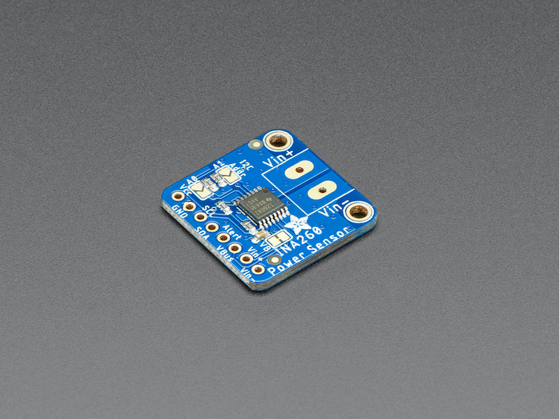
Image by Adafruit
Overview
The INA260 can measure voltages up to 36V DC and current up to 15A continuously! I am planning on using three of these in my up coming project.
I will be following Adafruit’s guide on how to use the INA260 board along with my own guide on using the Adafruit MCP2221A board.
Soldering on the headers and terminal block
I will be using the modules in a project and not on a breadboard, thus I will be soldering the headers to point out to the top (like a Raspberry Pi’s GPIO).
I placed the headers inside of a breadboard with the longer leads going into the breadboard.
Then placed the INA260 on top of the headers and soldered them in place.
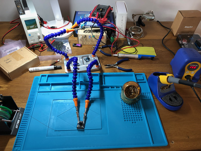
Next I removed the module from the breadboard and used my Third Hand tool to hold the module while I soldered on the terminal block.
Initial I2C testing
I will be using the Adafruit MCP2221A breakout board to communicate via I2C to the Adafruit INA260 board.
Please see my post about the Adafruit MCP2221A breakout for how I setup Python projects like these on my Mac.
My git repo for this module can be found here.
- Created a new branch in git and copied the mcp2221a directory as a start.
- Setup a Python virtual environment and install the required pip dependencies for the MCP2221A.
$ ./new-project.sh
$ ./install-requirements.sh
- I connected the INA260 to the MCP2221A using Female to Male jumper cables. In the picture below GND = Black, VCC 3V = White, SCL = Grey and SDA = Purple.
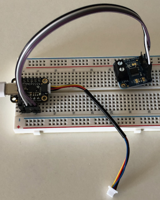
- Connect to the computer and run the I2C scan program.
# Active the venv and export the required environment variable for Blinka
$ source source.sh
(venv)$ cd examples
(venv)$ python3 i2c-scan.py

I2C addresses found: ['0x40']
- Hooray! That is a good sign that I did not damage the chip during the soldering process.
- Install the Adafruit CircuitPython INA260 library.
(venv)$ pip3 install adafruit-circuitpython-ina260
(venv)$ ./update-requirements.sh
- Create a file named
measure.py.
# Source from: https://learn.adafruit.com/adafruit-ina260-current-voltage-power-sensor-breakout/python-circuitpython
# SPDX-FileCopyrightText: 2021 ladyada for Adafruit Industries
# SPDX-License-Identifier: MIT

import time
import board
import adafruit_ina260

i2c = board.I2C()
ina260 = adafruit_ina260.INA260(i2c)
while True:
    print(
        "Current: %.2f mA Voltage: %.2f V Power:%.2f mW"
        % (ina260.current, ina260.voltage, ina260.power)
    )
    time.sleep(1)
- Run the program
(venv)$ python3 measure.py

Current: 0.00 mA Voltage: 0.00 V Power:0.00 mW
Current: 0.00 mA Voltage: 0.00 V Power:0.00 mW
Current: 1.25 mA Voltage: 0.00 V Power:0.00 mW
Current: 0.00 mA Voltage: 0.00 V Power:0.00 mW
Current: 1.25 mA Voltage: 0.00 V Power:0.00 mW
Current: 1.25 mA Voltage: 0.00 V Power:0.00 mW
Measure a simple circuit
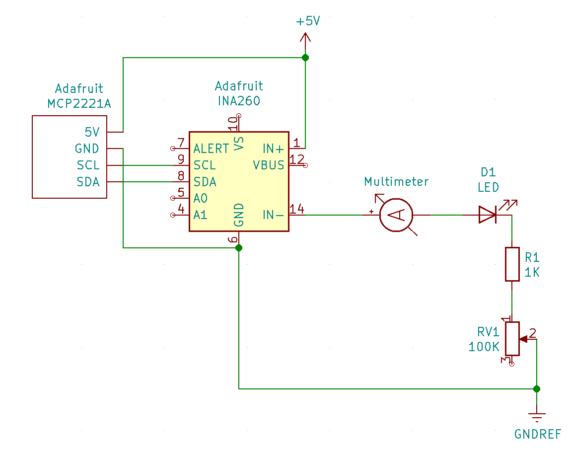
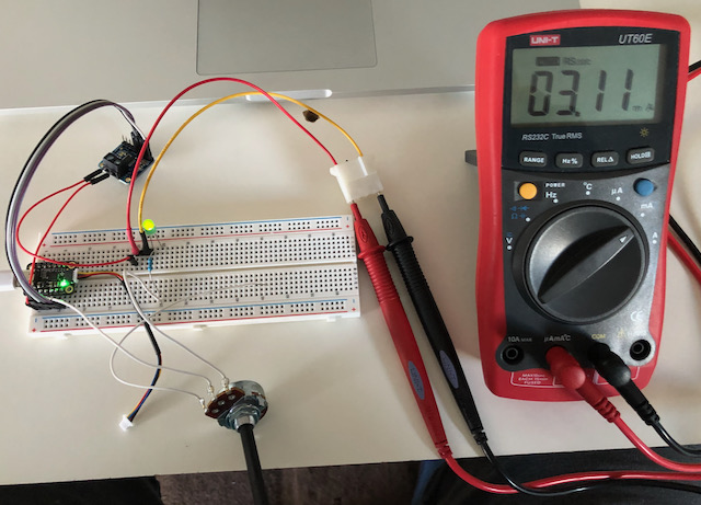
I built a very simple LED circuit powered from the 5V output from the Adafruit MCP2221A that passes through the Adafruit INA260 so that the current draw can be measured. The multimeter is also placed in the circuit to measure the current.
It is basically a LED connected to a 1K resistor. The potentiometer is there so that I can tweak the current draw and verify that the INA260 picks up the change.
- Run the
measure.pyprogram.
(venv)$ python3 measure.py
Current: 2.50 mA Voltage: 5.04 V Power:10.00 mW
Current: 2.50 mA Voltage: 5.04 V Power:10.00 mW
Current: 3.75 mA Voltage: 5.04 V Power:30.00 mW
Current: 3.75 mA Voltage: 5.04 V Power:10.00 mW
Current: 3.75 mA Voltage: 5.04 V Power:10.00 mW
Current: 5.00 mA Voltage: 5.04 V Power:10.00 mW
Current: 5.00 mA Voltage: 5.04 V Power:10.00 mW
Current: 2.50 mA Voltage: 5.04 V Power:10.00 mW
Current: 3.75 mA Voltage: 5.04 V Power:10.00 mW
Current: 5.00 mA Voltage: 5.04 V Power:10.00 mW
Current: 5.00 mA Voltage: 5.04 V Power:10.00 mW
Current: 3.75 mA Voltage: 5.04 V Power:10.00 mW
- NOTE: The INA260 has a resolution of 1.25mA.
- Repeated the test for the other INA260 modules that I bought.
Change the I2C address
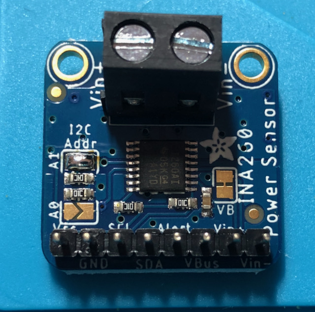
Each INA260 can be configured to have one of the following I2C addresses: 0x40, 0x41, 0x44 and 0x45. The default is 0x40. See Adafruit’s pinout for more information.
I will be using 3 of the modules in a project and thus will have one that uses the default address of 0x40 and the other two will be 0x41 and 0x44.
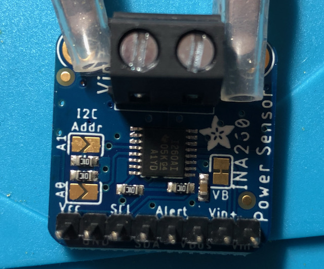
- To get the address 0x41 I will need to bridge solder over the two pads labelled A0.
- Verify
$ python3 i2c-scan.py
I2C addresses found: ['0x41']
- To get the address 0x44 I will need to bridge solder over the two pads labelled A1.
- Verify
$ python3 i2c-scan.py
I2C addresses found: ['0x44']
- In order to take measurements from the correct module, you will need to specify the I2C address in the Python code like this:
ina260 = adafruit_ina260.INA260(i2c, address=0x41)
Reference
-
Adafruit INA260 CircuitPython library.
- It is well worth reading the INA260 data sheet and going through the Adafruit library code because the INA260 can also be programmed to send out alerts or do one shot calculations.
- Adafruit CircuitPython.