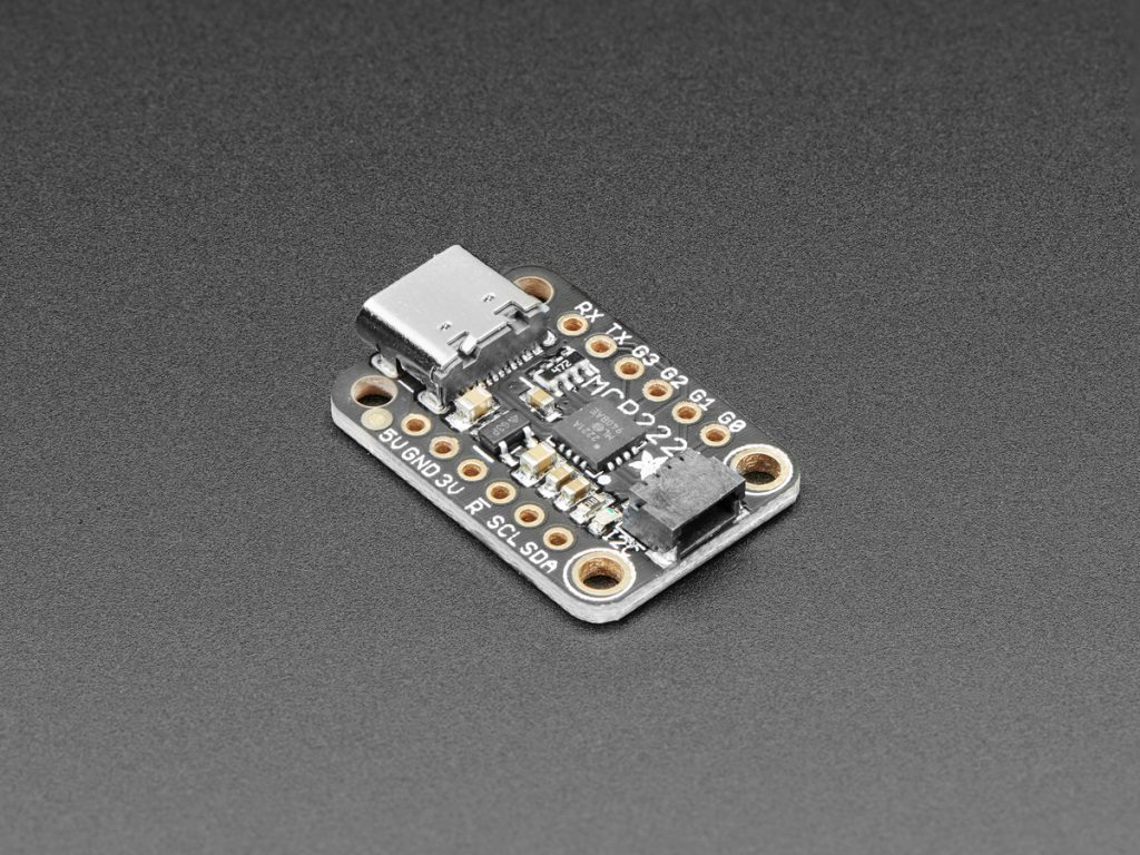
Image by Adafruit
Overview
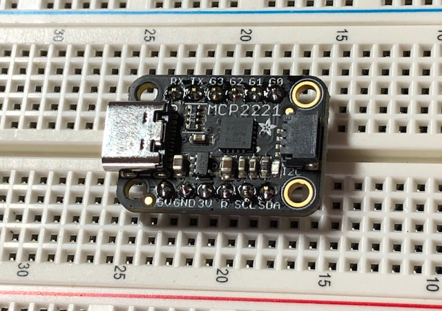
I came across the Adafruit MCP2221A breakout while I was ordering some components from The PiHut and what makes this little board amazing is that it allows you to connect a computer directly to I2C devices and thus skip the "middle microcontroller".
The MCP2221A allows you to connect via USB to an I2C bus and also comes with 4x GPIO, 3x ADC and one DAC.
My plan is to use this for testing various I2C devices as well as write the initial software I require directly and then convert it over to the controller of my choice later.
You can buy them from the following links:
I will be following Adafruit’s guide on how to set this little fella up on my Mac and most of the code examples come directly from them.
Installing prerequisite software
- Ensure I have a working Python 3 setup.
$ python3 --version
Python 3.9.6
- You can follow my guide on how I have setup Python 3 on macOS Big Sur. NOTE: At the moment I am still using an Intel based Mac and I do know not all 3rd party libraries work out of the box on M1 Macs.
- Created a new git repo that I want to start using for storing any software and tests for new Electronic modules that I buy and play with.
- Created a new branch in the repo.
- I will be using a Python virtual environment and my scripts to setup a new project.
$ mkdir -p adafruit/mcp2221a
$ cd adafruit/mcp2221a

# Copied the files from https://github.com/andrejacobs/scripts/tree/main/Python/base
$ ./new-project.sh
$ source ./venv/bin/activate
(venv)$ pip3 install hidapi
(venv)$ pip3 install adafruit-blinka
- Update the dependencies required when this project is installed in a new location (someone else’s machine)
(venv)$ ./update-requirements.sh

(venv)$ cat requirements.txt
Adafruit-Blinka==6.15.0
Adafruit-PlatformDetect==3.16.1
Adafruit-PureIO==1.1.9
hidapi==0.11.0.post2
pyftdi==0.53.3
pyserial==3.5
pyusb==1.2.1
- Created a script
source.shthat will source the virtual environment as well as set the required Blinka environment variable.
#!/bin/bash
source venv/bin/activate
export BLINKA_MCP2221="1"
- Run and verify the variable is set as expected. NOTE: You will need to source this every time you start a new shell session.
$ source source.sh
(venv)$ echo $BLINKA_MCP2221

1
- Connect the Adafruit MCP2221A breakout and check that Blinka works.
(venv)$ python3
>>> import board
>>> dir(board)
['G0', 'G1', 'G2', 'G3', 'I2C', 'SCL', 'SDA', '__blinka__', '__builtins__', '__cached__', '__doc__', '__file__', '__loader__', '__name__', '__package__', '__repo__', '__spec__', '__version__', 'ap_board', 'board_id', 'detector', 'pin', 'sys']
- Final preflight checks.
# Check all the attached USB devices
(venv)$ python3
>>> import hid
>>> hid.enumerate()
...
'release_number': 256, 'manufacturer_string': 'Microchip Technology Inc.', 'product_string': 'MCP2221 USB-I2C/UART Combo', 'usage_page': 65280, 'usage': 1, 'interface_number': 2}

>>> device = hid.device()
>>> device.open(0x04D8, 0x00DD)
>>> # No errors mean it works

# Check the exported environment variable can be read by Python
>>> import os
>>> os.environ["BLINKA_MCP2221"]
'1'

>>> device.close()
>>> exit()
- Disconnect the breakout from the computer.
Testing GPIO
First test is to just do the classic hello world of Electronics and that is to blink an LED. I will be building the circuit from Adafruit.
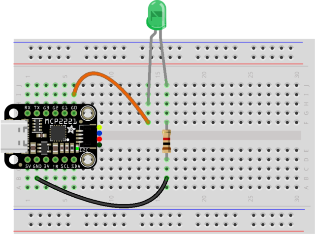
Image by Carter Nelson: https://learn.adafruit.com/assets/85988
- Create a Python file named
blink.pyand run it usingpython3 blink.py
import time
import board
import digitalio

led = digitalio.DigitalInOut(board.G0)
led.direction = digitalio.Direction.OUTPUT

while True:
    led.value = True
    time.sleep(0.5)
    led.value = False
    time.sleep(0.5)
- The LED is connected to port G0 and ground via a 1K resistor. The program writes a digital 1 (positive voltage) to turn the LED on and a digital 0 (zero voltage) to turn the LED off.
- Next test is to be able to read from the GPIO and write to the GPIO using a button and a LED.
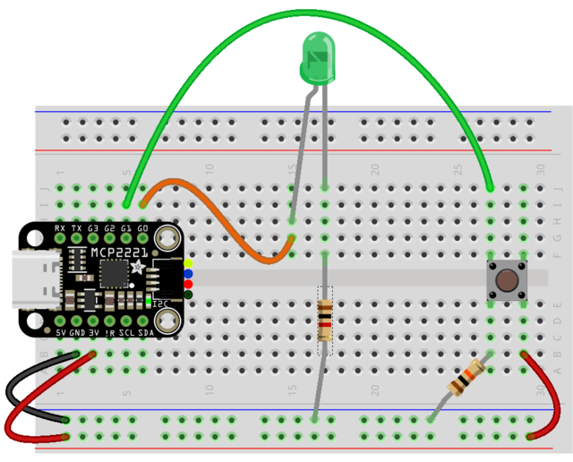
Image by Carter Nelson: https://learn.adafruit.com/assets/86096
- Create a file named
led-switch.pyand run it usingpython3 led-switch.py.
import board
import digitalio

led = digitalio.DigitalInOut(board.G0)
led.direction = digitalio.Direction.OUTPUT

button = digitalio.DigitalInOut(board.G1)
button.direction = digitalio.Direction.INPUT

while True:
    led.value = button.value
- The button is connected to port G1 and a 10K pulldown resistor to keep the port receiving a digital 0 until the button is pressed, which then pulls the G1 value to the 3V supply. The LED connected to port G0 reflects what ever input is received from port G1. Switch On = G1 On = LED On and vice versa.
Soldering on the headers
There is only so much I can fiddle with test hooks before I end up shorting pins and blowing the board up. Time to solder on the supplied header pins.
The Adafruit board nicely came with male header pins and it was only a matter of breaking off 2x 6 pins and I still had 4 pins left over for another project.
Using a breadboard to solder on headers is the best trick in the book!
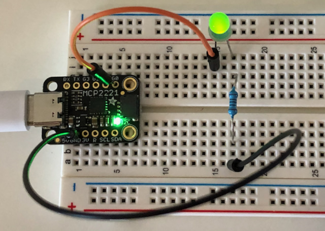
After that I reconnected up the blinking LED circuit to test I didn’t fry any non starchy chips in the process. Hooray it all still works!
Testing ADC
It is so handy that this little board comes with 3x analog inputs.
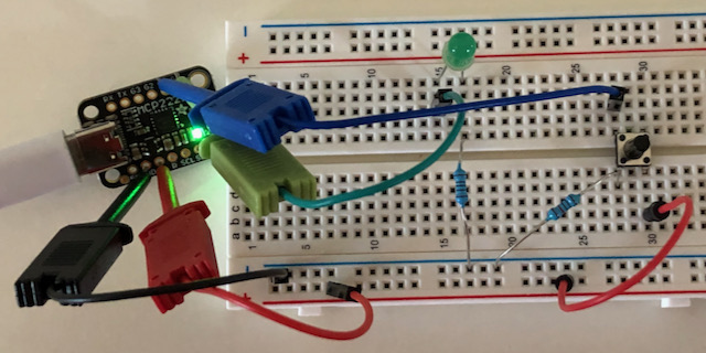
To test the analog signal I will be following the Adafruit example of setting up a voltage divider that you can control through a potentiometer. Their example used a 10K pot whereas I will be using a 100K one that happen to have lying around here used in previous experiments.
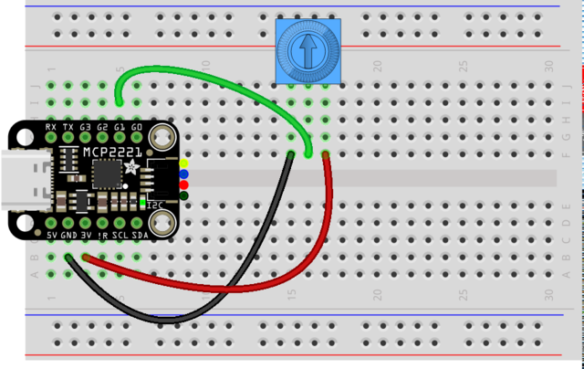
Image by Carter Nelson: https://learn.adafruit.com/assets/85993
- Create a file named
analog.pyand run it usingpython3 analog.py
import time
import board
from analogio import AnalogIn
knob = AnalogIn(board.G1)
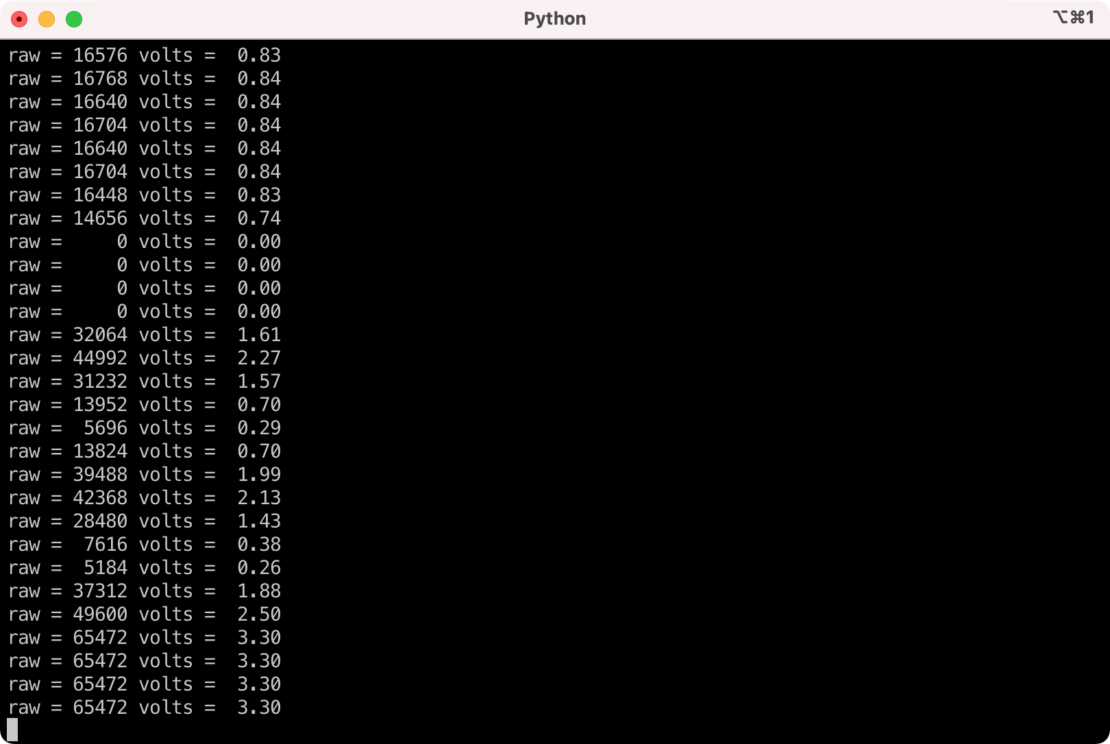
def get_voltage(raw):
return (raw * 3.3) / 65536
while True:
raw = knob.value
volts = get_voltage(raw)
print("raw = {:5d} volts = {:5.2f}".format(raw, volts))
time.sleep(0.5)
- The G1 port is used to read in a analog value supplied by varying the resistance of the potentiometer.

Time for the money shot: Testing I2C
Adafruit has a really nice tutorial about I2C and an example of how to scan for connected I2C devices.
I connected a Grove-16×2 LCD that came as part of the Grove Starter Kit for Raspberry Pi Pico using an Adafruit Grove to STEMMA QT / Qwiic / JST cable.
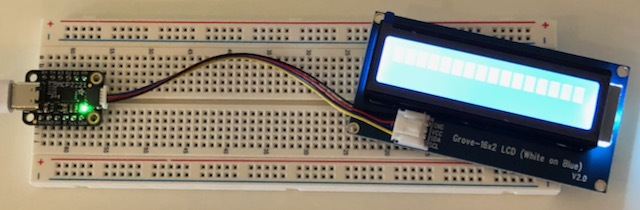
- Create a file named
i2c-scan.pyand run it usingpython3 i2c-scan.py
"""CircuitPython Essentials I2C Scan example"""
# If you run this and it seems to hang, try manually unlocking
# your I2C bus from the REPL with
#  >>> import board
#  >>> board.I2C().unlock()

import time
import board

i2c = board.I2C()

while not i2c.try_lock():
    pass

try:
    while True:
        print("I2C addresses found:", [hex(device_address)
              for device_address in i2c.scan()])
        time.sleep(2)

finally:  # unlock the i2c bus when ctrl-c'ing out of the loop
    i2c.unlock()
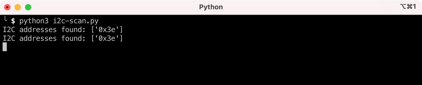
- This confirms that I2C devices can be found. I will leave it for now trying to write to the LCD module.
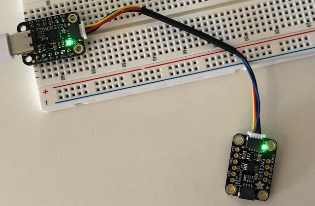
Reading temperature from the EM2101 PC fan controller
- Next I will connect an Adafruit EM2101 I2C PC Fan Controller and Temperature Sensor and see if I can just read the built in temperature sensor. Controlling PWM (4 pin PC) fans will come in a later post for a project I am working on. The cable I am using is the STEMMA QT / Qwiic JST SH cable from The PiHut.
- I created a new directory for the em2101 and set it up the same way. You can find a copy in the github repo.
- Install the em2101 CircuitPython library.
(venv)$ pip3 install adafruit-circuitpython-emc2101
- Connect the electronics up and to the Mac. Run the
i2c-scan.pyprogram.
(venv)$ python3 i2c-scan.py
I2C addresses found: ['0x4c']
- Create a file named
temp.pythat will only be used for reading the internal temperature sensor.
import time
import board
from adafruit_emc2101 import EMC2101

i2c = board.I2C()
emc = EMC2101(i2c)

while True:
    print("Internal temperature:", emc.internal_temperature, "C")
    time.sleep(0.5)
- Run the program
(venv)$ python3 temp.py
Internal temperature: 22 C
Internal temperature: 21 C
Internal temperature: 22 C
Internal temperature: 21 C
Internal temperature: 21 C
Internal temperature: 21 C
Internal temperature: 21 C
Internal temperature: 21 C
Conclusion
I am really liking this Adafruit MCP2221A breakout board! Being able to connect I2C sensors almost directly to my Mac is a dramatic speed up in testing and learning about different modules I want to use in my projects. Think I will order a couple more of these guys.
1 comment on “Talk to I2C devices directly from a Mac using the Adafruit MCP2221A Breakout”
Comments are closed.